Secrets of Antigravity Propulsion (30 page)

8
MICROWAVE PHASE CONJUGATION
8.1 • PHASE-CONJUGATE MICROWAVE PROPULSION
As mentioned in the previous chapter, my contact Tom had received a letter from a friend of his supervisor, a fellow we have called Don.
In 1974, when Tom received this letter, Don was actively involved in Project Skyvault.
The letter gave only a rough sketch of the project’s microwave propulsion technology, since much of that work was then still classified.
Nevertheless, Don gave enough information that, shortly after hearing Tom’s story, I was able to come to an important conclusion about a key aspect of the craft’s microwave beam propulsion technology.
I was able to connect it to a field of optics research that in 1994 was just beginning to emerge in the open literature, but which apparently had been secretly under full development for aerospace applications back in the early 1950s.
Before discussing this optical phenomenon, called
phase conjugation
, and how it might be applied to vehicle propulsion, let us summarize some additional details that Don provided about the propulsion system.
Don said that the microwave energy from the microwave amplifier cavity was directed into a horn-shaped waveguide that controlled or shaped the wave radiation pattern.
Although he did not specifically mention it, this horn antenna was most likely situated between the iris and the ceramic convex lens that, as Murray had described, was used to control the diameter of the beam.
After leaving the lens, the microwave beam was allowed to pass through the air to a target area, which was presumably a ground surface location.
Microwaves that reflected back up to the vehicle from this target region were then allowed to enter a cavity that contained a mixer diode (figure 8.1).
There they were mixed with a portion of the outgoing microwave beam that had been locally diverted from the craft’s beam generator.
A mixer diode is a radar-absorbing material with nonlinear electromagnetic characteristics that is able to combine waves of slightly differing frequencies to produce a more complex wave having frequencies that are the sum and difference of the two frequencies.
Interestingly, one material that has such nonlinear properties is barium titanate, the piezoelectric ceramic that Brown employed in his experiments.
Don noted that a stable DC-voltage source was connected across the mixer diode to bias it and that the Gunn diode oscillator was biased in a similar manner.
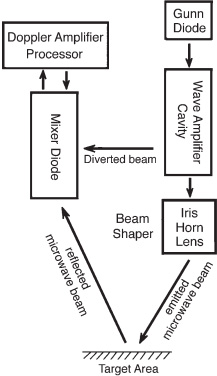
Figure 8.1.
Murray’s description of the microwave transmitter/mixer detector used in Project Skyvault.
(P.
LaViolette, © 2006)
Don described two types of antigravity microwave systems.
The simpler version, called a homodyne, used the same conduits for both transmitting and receiving.
He commented that this system “suffered from a lack of range” since its microwave beam typically targeted at no more than thirty miles.
The second type of configuration, which he called the “Micro-X unit,” used separate transmitting and receiving antennae and presumably could achieve a greater targeting range.
It was probably named the Micro-X because it originally operated in the X microwave band, which extends from 8 to 12 gigahertz.
Up to this point, the apparatus that Don described sounds much like a basic radar unit.
In the case of radar, the transmitter emits a powerful microwave pulse that then reflects back from the distant target and enters the radar receiver.
This weak reflected wave is then combined in the radar’s mixer chamber with a portion of its original outgoing signal.
Suppose we let
f
o
represent the reference frequency of the outgoing signal and f represent the return signal that reflects from a target such as a distant aircraft.
If the target is moving, the return signal frequency
f
will be slightly different from the original outgoing signal
f
o
, for an approaching target
f
>
f
o
and for a receding target
f
<
f
o
.
The two frequencies will differ by an amount Δf, equal to twice the Doppler frequency shift, that is Δ
f
=
f
–
f
o
= 2
f
o
v/c
, in which v is the velocity of the target relative to the radar transceiver and c is the velocity of light.
A frequency φ (
phi
), equal to this frequency difference, φ = Δ
f
, would come out of the radar’s mixer chamber.
Its magnitude and sign would indicate how fast the target is moving and whether it was approaching or receding.
The greater the frequency difference, the greater would be the relative velocity inferred for the target.
However, the nonlinear media used in a radar mixer, as it turns out, can also act as a phase conjugate mirror.
That is, when illuminated with a radar pulse echo coming in from the target, it produces an outgoing microwave pulse that exactly retraces the path of the incoming target echo signal.
This is very different from normal mirror reflection.
Consider an example in which visible light reflects from a conventional mirror.
When a laser shines its beam on a target object and some of that light scatters off from the object and strikes a conventional mirror at some angle to its surface, that light will then reflect away from the mirror’s silvered surface at a similar angle.
The reflected light will continue on a divergent path that takes it increasingly farther from the mirror and the light-scattering object (see figure 8.2a).
In the case of a phase conjugate mirror, on the other hand, the silvered mirror surface is replaced with a translucent piezoelectric crystal such as barium titanate, which has nonlinear optical properties.
Again, consider an example in which a laser illuminates the target object and some of the light that scatters from the target enters this crystal, but in addition, part of the light coming directly from the laser is diverted and made to enter the crystal as beam P
1
.
This laser beam passes through the crystal and reflects back from a mirror on the other side to form a second beam, P
2
, propagating in the opposite direction (see figure 8.2b).
These counterpropagating beams are called the
pump beams
.
The light that scatters from the target object toward the crystal is called the probe beam.
The light waves forming the probe beam enter the interior of the crystal and interact there with the counterpropagating pump beams.
The interaction of the probe beam with each of the pump beams produces an interference pattern that alters the index of refraction within the crystal to form a complex pattern of light-refracting surfaces collectively called a
holographic amplitude grating.
The holographic grating formed by pump beam P
2
then refracts the oppositely directed pump beam P
1
to form an outgoing
phase conjugate beam
.
In contrast, the grating formed by beam P
1
refracts beam P
2
to again form an outgoing phase conjugate beam, with complementary characteristics.
This combined phase conjugate beam is represented in figure 8.2b by the gray wave fronts.
The phase conjugate beam has the special attribute that its light waves move outward from the crystal along trajectories that precisely retrace the trajectories that had earlier been followed by the probe beam’s incoming waves.
Hence, the phase conjugate beam converges back to the original light-scattering locations on the target object, and from there its waves rescatter back to the original laser beam light source.
The phase conjugate mirror, in effect, generates a new set of light waves that have the same angle, wave shape, and phase as the incoming light waves scattered from the target object but travel in a reverse direction, moving back toward the target.
The effect appears as though time had been made to run backward, causing the incoming scattered light waves to reverse in their tracks.
However, here the effect is accomplished with time running forward as it usually does and with light waves different from the incoming waves since the incoming waves are what are generating the grating pattern.
Thus, unlike conventional mirror reflection, in which the reflected light continues to spread out into the surrounding environment, with phase conjugate reflection the light stays bottled up, confined to a beam that extends among the laser light source, its illuminated light-scattering object, and the nonlinear medium of the phase conjugate resonator.
Since the light waves have no immediate exit, the energy trapped in this phase conjugate resonator can build up to very high intensities.
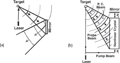
Figure 8.2.
Comparison of an ordinary mirror and a phase
conjugate mirror.
(a) Light waves reflecting from an ordinary mirror.
The black wave fronts represent the incident rays and the gray wave fronts represent the reflected rays.
(b) Light waves reflecting from a phase conjugate mirror.
The black wave fronts represent the incident rays and the gray wave fronts represent the phase conjugate rays that travel “in reverse,” converging toward the upper left.
The phase conjugate beam is generated from the interaction of the incoming probe beam with the two counterpropagating pump beams, P
1
and P
2
.
Physicists have come to call this arrangement a
four-wave mixer
since four beams intersect in the nonlinear medium: the incoming probe beam, the two counterpropagating pump beams, and the outgoing phase conjugate beam.
Although the probe beam initially would be relatively weak, energy supplied by the two pump beams would emerge from this four-wave mixer as a powerful outgoing phase conjugate beam.
Upon entering the laser resonator cavity, this phase conjugate beam would stimulate a more powerful outgoing laser beam that would be specifically directed toward points on the target that preferentially scatter light into the four-wave mixer.
As a result, the probe beam entering the mixer crystal would progressively increase in intensity.
Over time, a high-intensity light path would resonantly build up among the laser, the target object, and the four-wave mixer, and very little if any of the laser’s light would be scattered into the environment.
The second law of thermodynamics tells us that in closed systems, order always tends toward disorder, that is, it predicts that light scattered from an object should disperse into space and eventually dissipate its energy.
This is not so with light striking a phase conjugate mirror.
The grating records the information carried by the incoming probe beam concerning where its light waves originated and in turn refracts (steers) the pump beam to create an outgoing phase conjugate beam whose waves precisely retrace the paths that had been followed by the incident rays of the probe beam.
Thus, a state of initial disorder is made to tend toward a subsequent state of greater order.
The scattered light is returned in a more concentrated state toward the point from which it emerged.