Secrets of Antigravity Propulsion (27 page)

In either case, by embedding such particles in his dielectric, Brown would have been producing domains having electric and/or magnetic resonances over a range of microwave frequencies, which, in turn, would have created regions where the dielectric’s permittivity and/or permeability would be negative.
So, many decades before the University of California San Diego group demonstrated negative index of refraction in a metamaterial, Brown was experimenting with similar artificial materials but with the aim of enhancing the thrust in AC-excited dielectrics.
He made no mention of resonances or negative
ε and μ values, so maybe he was not entirely aware of all the reasons why these semiconductor particles were improving the lift of his dielectrics.
He was conducting these investigations almost a decade after the Project Skyvault scientists had begun their highly classified early experimentation with similar materials, so it is not surprising that Admiral Rickover advised him to drop his electrogravitic investigations.
Brown was apparently getting too close to work already in progress in Project Skyvault.
Interestingly, in the early 1950s, Brown was conducting electric disc experiments at his Los Angeles laboratory, which was in the same metropolitan area where Project Skyvault was under way.
One wonders if he had heard rumors of the Skyvault work.
Metamaterials have strange new properties not normally seen in nature.
First of all, they refract electromagnetic waves more strongly than naturally occurring materials that have a positive index of refraction.
The diagrams in figure 7.4 compare the trajectories for a beam passing: (
a
) through a medium having a positive index of refraction and (
b
) through a medium having a negative index of refraction.
Regardless of their refractive index, materials with a positive index always refract incident rays into the right quadrant, which lies on the opposite side of the line that is normal to the refracting surface.
Materials with a negative index (e.g., n = –1) always refract incident rays into the left quadrant, which lies on the same side of the normal line.
For this reason, materials with a negative index of refraction are sometimes termed “left-handed materials.”
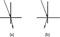
Figure 7.4.
Refraction of a light ray in a
material having (a) a positive index of
refraction and (b) a negative index
of refraction.
Another unusual property of left-handed materials is that they can be used to make a lens that resolves far greater detail than one made out of a material with a positive index of refraction.
Such a lens can depict details even smaller than the wavelength of light used to illuminate the object and can be made much lighter compared with the bulging convex lenses of conventional optical devices.
Metamaterials refract light so strongly that a planar sheet serves as a convex lens, with the incident rays coming to a focus within the sheet.
In order to allow the beam to come to a focus outside the lens, the metamaterial must be fabricated in a concave shape.
Also, metamaterials can be designed to be total absorbers of the incident radiation, making them ideal as radar-absorbing materials.
In 2003, Yong Zhang and coworkers at the National Renewable Energy Laboratory demonstrated negative refraction in a common ferroelastic material made from a “twinned” alloy containing yttrium, vanadium, and oxygen.
12
They found that this crystal would negatively refract light of any frequency with no back reflection at the medium interface, which raises the possibility of making reflection-free optical lenses.
The U.S.
Air Force Research Laboratories has supported a number of research projects with the recent upsurge of interest in metamaterials.
Also, the Defense Sciences Office (DSO) of the Defense Advanced Research Projects Agency has an ongoing program for funding metamaterials research.
In fact, as of July 2006, the description of its metamaterial program that DSO gave on its website frankly stated that one of the intentions of its research program was to develop magnetic metamaterials for “electric drive and propulsion”:
Metamaterials are engineered composites that exhibit superior properties not observed in the constituent materials or nature.
The objective of the MetaMaterials Program is to develop, fabricate, and implement new bulk metamaterials that will fill the tremendous voids that exist in the design space for a number of applications of critical importance to the military Services.
In particular, this program will develop (1) magnetic metamaterials for power electronics and
electric drive and propulsion
, and (2) microwave and optical metamaterials for antenna, radar, and wireless communication applications.
13
Thus, the notion that Rocketdyne was developing metamaterials in the early 1950s for an aerospace electric propulsion application seems plausible.
Interestingly, by early November 2007, DSO had removed this webpage and replaced it with a rewritten version that made no mention of its interest in using negative index materials for propulsion.
It now mentions only the application of negative index materials to optics and to the development of “lightweight, compact RF structures,” with an additional broad reference to “practical application” of the technology.
Obviously, sometime between July 2006 and November 2007 Defense officials must have decided that the propulsion part of their metamaterial program was too sensitive to be mentioned publicly.
One wonders whether this website modification might have been triggered by their becoming aware of the impending publication of this book.
In early August 2007, a draft catalog copy announcing its forthcoming publication and noting its disclosure of Project Skyvault had been e-mailed to me for author review and by early October 2007 the finalized copy of the book announcement had been posted on the publisher’s website.
7.3 • SAWTOOTH WAVES
Murray said the Skyvault team found that the kind of response they got with a given material depended on the particular wave shape used.
They achieved the best results with a sawtooth-shaped waveform consisting of asymmetrical triangular waves that have either a steep voltage rise or a steep voltage decline.
As noted in chapter 6, the shock wave pulses produced by Podkletnov’s gravity impulse beam generator have a sharp rise at their leading edge and are capable of generating strong repulsive forces.
Tesla also observed longitudinal repulsive forces being produced by the energy wave shocks radiated from his magnifying transmitters.
Subquantum kinetics predicts that the magnitude and direction of the accelerating force depend critically on the shape of the sawtooth wave since different wave shapes generate different virtual-charge distributions, which in turn generate differing gravity potential gradients.
Consider, for example, the wave shape shown in figure 7.5a.
This plots the voltage potential profile, φ
E
(r), for a capacitor that is gradually charged through a resistance, R
1
, and then rapidly discharged through another resistance, R
2
, in which R
1
is greater than R
2
.
This produces a wave with asymmetrical rise-and-fall slopes (see figure 7.5 legend).
When the x axis is chosen to indicate distance instead of time, the graph shows how the electric potential gradient varies with distance from the front to the back of the wave, in which the wave travels from right to left at the speed of light.
The sawtooth profile in figure 7.5b (left) is a similar type of waveform, but one depicting voltage potential in a capacitor that charges rapidly and then discharges more gradually.
In effect, the values for resistances R
1
and R
2
have been interchanged from those used in generating the curve shown in figure 7.5a.
In this second example, R
1
is less than R
2
.
Profiles 7.5c and 7.5d in figure 7.5 plot the corresponding gravity potential profiles, φ
g
(r), that would accompany each of these electric potential waves, based on the assumption that the virtual-charge densities that this wave creates generate corresponding virtual-mass densities and associated gravitational potentials.
These are obtained by taking the negative second derivative of the voltage potential equation plotted in figure 7.5a or figure 7.5b.
This is in accordance with the subquantum kinetics electrogravitic relation specified by equation 7 in chapter 4.
The wave profile shown in figure 7.5a that charts a gradual voltage ascent followed by a rapid voltage decline is seen in the gravity potential plot, figure 7.5c, to initially produce a weak attractive gravitational force (small arrow) followed by a very strong repulsive force (large arrow).
For the particular waveform plotted here, the repulsive impulse (force multiplied by time) is twenty-five times greater than the attractive impulse, even though the repulsive impulse lasts only about one-fifth as long.
Thus, this wave would produce a net repulsive force on material bodies that it passes through.
Changing the wave shape to that shown in figure 7.5b yields a gravity potential wave that has a very steep attractive gravity gradient at its leading edge and a gradual repulsive gradient at its trailing edge and produces a net attractive gravitational force (see figure 7.5d).
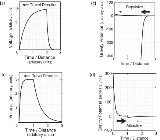
Figure 7.5.
(a) left: Voltage profile for an asymmetrical RC-RC-type sawtooth wave having a gradual exponential voltage rise and rapid exponential voltage fall.
(b) Voltage profile for an RC-RC wave adjusted to have a rapid exponential voltage rise and gradual voltage fall.
(c) Gravity potential profile generated by the virtual-charge distribution of the RC-RC wave shown in 7.5a.
(d) Gravity potential profile generated by the virtual-charge distribution of the RC-RC wave shown in 7.5b.
Arrows in 7.5c and 7.5d indicate the magnitude and direction of the resulting electrogravitic thrust.
(P.
LaViolette, © 2007)
The voltage potential in 7.5a is represented by the following equations: V = 3(1 – e
-2x
) for voltage ascent and V = 3e
-10x
for voltage descent, in which x represents time from left to right or distance from the front to the back of the wave.
Thus, the wave has a descent rate that is five times its rate of ascent.
The voltage in 7.5b is represented by the following equations: V = 3(1 – e
-10x
) for the voltage ascent and V = 3e
-2x
for the voltage descent.
Thus, the exponents in the equation for figure 7.5a have been interchanged in producing the equation for figure 7.5b.
The corresponding gravity-potential profiles, 7.5c and 7.5d, were plotted by taking the negative second derivative of these voltage relations.
If the wave was made symmetrical so that its voltage rose at the same rate as it fell (R
1
= R
2
), then the attractive gravitational force produced during passage of the wave’s leading edge would just balance the repulsive force produced during passage of its trailing edge, and as a result, the net gravitational force would be zero.
If the polarity of the wave shown in figure 7.5a was changed so that its voltage was negative instead of positive, as shown in figure 7.6a, then the electrogravitic coupling relation predicts that the gravitational potentials would also reverse polarity, as shown in figure 7.6c.
The gravity gradients would now change sign, making the net thrust attractive rather than repulsive.
The same gravitational polarity reversal would occur if the profile shown in figure 7.5b was to go negative.
Instead of producing a net attractive force, it would produce a net repulsive force.
Stavros Dimitriou, professor of electrical engineering at the Technical Education Institute in Athens, Greece, has investigated whether capacitors energized with sawtooth waves in the radio frequency range might exert gravitational forces on nearby masses.
14,
15,
16
In his master’s thesis, he discussed an electric intensity waveform having shapes similar to those shown in figures 7.5 and 7.6, which he named an RC-RC waveform.
17
The RC acronym implies that the wave shape is determined by a capacitor of capacitance (C) being charged through a resistor of resistance (R).
His electrogravitic wave research is discussed in chapter 11.
Another waveform shape that Dimitriou has investigated is shown in figure 7.6b.
This one is similar to the RC-RC sawtooth wave shown in figure 7.5a, except that in this case voltage declines linearly, rather than exponentially.
*21
The wave’s voltage descent is created by discharging the charged capacitor through a constant-current (Norton) element; hence, Dimitriou refers to this type of waveform as an
RC-Norton
wave.
The subquantum kinetics electrogravitic coupling relation predicts that such a wave would produce an attractive gravitational force during its voltage ascent and no gravitational force on voltage descent.
That is, since voltage declines linearly, its second derivative would be zero.
Hence, no virtual charge and no mass density would be produced during this decline phase.
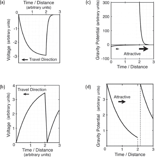
Figure 7.6.
(a) Voltage of an asymmetrical RC-RC-type wave having a gradual exponential voltage drop and rapid exponential voltage rise.
(b) Voltage of an RC-Norton sawtooth wave having a gradual exponential voltage rise and rapid linear voltage decline.
(c) Gravity-potential profile generated by the RCRC wave shown in 7.6a.
(d) Gravity-potential profile generated by the RC-Norton wave shown in 7.6b.
(P.
LaViolette, © 2007)
If the gravity field is generated primarily by the electrogravitic effects of virtual charge, then a triangular sawtooth wave having a linear voltage rise and fall should produce no gravitational thrust, either on the voltage ascent phase or on the voltage descent phase.
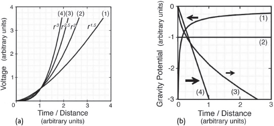
In another example, thrust will not be produced if the wave has a voltage profile that rises as the square of distance.
Such a profile would have a concave parabolic leading edge similar to that of profile 2 in figure 7.7a.
In this case, the negative second derivative of its r
2
voltage profile gives a negative gravity potential that remains constant over time (see profile 2 in figure 7.7b).
Hence, its gravity gradient would be zero, resulting in no force exertion.
If we change the exponent characterizing the wave’s profile so that the exponent is not equal to 1 or 2, but to a fraction or any other whole number, then the wave would be able to exert a gravitational force.
In the case in which the profile varies as r
1.5
, the gravity potential gradient creates a repulsive thrust in the same direction as the gravity wave’s motion (see curve 1 in figure 7.7b).
If the profile were to vary as r
2.5
, the gravity potential would develop a slope of opposite sign that would produce an attractive force opposed to the direction of wave motion (see curve 3 in figure 7.7b).
If the profile instead were to vary as r
3
, the gravity potential would develop a steeper slope that would produce an even stronger attractive force (see curve 4 in figure 7.7b).
The shock discharge emitted from Podkletnov’s superconducting cathode would similarly have been characterized by an exponential voltage rise at its leading edge, but one with a very large exponent.
Hence, such discharges would have produced much steeper gravity gradients and greater gravitational forces than those modeled here.
Also, being a negative voltage rise, the gravitational force exerted by Podkletnov’s beam is predicted by the electrogravitic coupling relation to be repulsive rather than attractive, as is observed.