Secrets of Antigravity Propulsion (22 page)

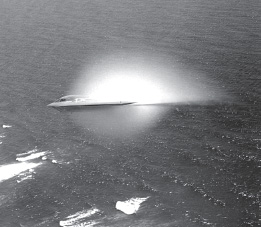
Figure 5.7.
A B-2 bomber flying through humid coastal air at transonic speeds with a vapor cloud condensing behind its bow compression wave.
(Photo by Bobbi Garcia, courtesy of the U.S.
Air Force Flight Test Center)
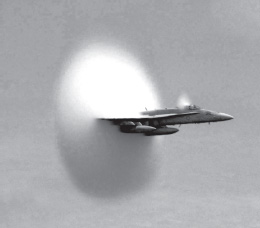
Figure 5.8.
Vapor cloud around an
F/A-18 jet fighter flying at transonic
speed.
(U.S.
Navy photo by Ensign
John Gay)
The B-2 is not quite as invisible to detection as is often claimed.
For example, its flame-jet generator exhaust could generate a radio noise signal.
If that’s so, the random high-velocity movement of negative ions present in the turbulent exhaust stream would produce radio wave noise emission.
This could explain the signal noise that one TV viewer reported at the time of one B-2 sighting.
Also, although invisible to radar detection at microwave frequencies, at lower frequencies such as are used in television broadcasting, the B-2 produces a distinct reflection.
Just like conventional low-flying airplanes, it causes a local distortion in the TV signals received by residential televisions.
In fact, during the war in Yugoslavia, Serbs were monitoring TV disturbance patterns over populated areas as a method of alerting them to when a B-2 was in the area and to determine where one might be located at any given time.
In retaliation, the Americans bombed their television transmitting tower.
5.3 • AC ELECTRIFICATION?
It is possible that the B-2 superimposes an AC signal on its DC bias potential.
The Aviation Studies “Electrogravitic Systems” report mentions using high-K dielectrics energized with 50,000 kilovolt-amps of power as a means for propelling a supersonic combat vehicle of the sort proposed in Project Winterhaven.
This clearly implicates the use of high-voltage AC.
So, we might venture that, in addition to the DC bias potential, a high-frequency AC field is applied between the wing leading edge and the rear exhaust ports.
If the excitation frequency was chosen to be 30 megahertz, then a quarter wavelength would have fit across the ten-meter distance from the exhaust ducts to the wing leading edge.
This would have allowed the applied AC field to resonantly build up to a high voltage potential, similar to what Brown was achieving with his electrokinetic apparatus.
This could be done with a high-voltage class C amplifier designed to automatically lock in on the wing’s resonant frequency.
By repeatedly charging and discharging the craft’s dielectric, the AC field would also have kept the craft’s dielectric from fully polarizing and building up an electric dipole moment that might cancel out most of the field propulsion thrust effects.
We might venture that the same AC energization technique may also be used to provide vertical thrust to the B-2, thereby allowing it to hover.
The B-2 is said to have a weight of about 158,000 pounds (72 metric tons) when empty and about twice that when fully loaded.
For a wing area of 460 square meters, this works out to about 16 grams per square centimeter empty or 32 grams per square centimeter when fully loaded.
By comparison, Brown’s 18-inch-diameter vertical electrokinetic thruster was generating an upward force of 125 grams when energized at 170 kilovolts.
This amounts to a lift of about 0.08 gram per square centimeter.
So, to generate a force sufficient to support the B-2, a thrust-per-unit area only four hundred times greater would be needed.
This could easily be accomplished simply by using a high-K dielectric for the thruster’s central insulator and energizing the device at a higher voltage.
The “Electrohydrodynamics” report mentions that thrust increased exponentially with voltage, according to the square or cube of voltage.
Moreover, the data Bahnson presented in his 1965 patent indicates that thrust on an AC-energized test rig increased according to the 2.6 power of voltage.
Extrapolating this, we find that Brown’s vertical thruster would deliver greater than a hundred times more thrust if it were energized at 1,000 rather than 170 kilovolts.
Also, if Brown had replaced his Pyrex insulator with a material such as barium titanate, having a higher dielectric constant and higher mass density, this would have boosted the thrust by an additional thirty-two-fold.
So instead of just 125 grams of force, Brown’s thruster could have produced an amazing 400 kilograms of force.
If 380 of these asymmetrical capacitors were distributed over the B-2’s lower wing surface, they would collectively produce an upward thrust of 152 tons, sufficient to loft a fully loaded B-2.
Brown is likely to have made similar thrust projections in proposing his electrogravitics idea to the military.
We may be erring on the low side in making this estimate, since dielectrics are known to exist that have K values more than four times higher than the K value of barium titanate.
*16
To ensure that the thruster electrodes did not arc over at these high voltages, the interior space of the arcuate canopy (shown in figure 3.2) could be filled with a low-K insulator.
The entire thruster together with its high-strength canopy, central high-K dielectric, surrounding low-K insulator, and high-voltage step-up transformer might weigh only 20 kilograms, which would amount to 2 percent of the thrust that the device would be producing.
The “Electrohydrodynamics” report states that under vacuum conditions, Brown’s electrokinetic capacitor drew just 2 microamps of current at 250,000 volts.
At the 1,000-kilovolt potential proposed for the B-2 thrusters, this leakage current would probably extrapolate to about 30 microamps, or about 30 watts of power.
Adding in the power requirement for the AC microwave source used to excite the negative electrode, the total power consumption might come to about 100 watts per thruster, or about 38 kilowatts total.
Given that each thruster would be yielding 400 kilograms of force, this amounts to a thrust-to-power ratio of about 40,000 newtons per kilowatt, or about 2,700 times that of a jet engine.
As an alternative to Brown’s electrokinetic thrusters, the B-2 could be lofted by a series of Lafforgue field propulsion thrusters of the type discussed in chapter 12.
Theoretical projections suggest that such a capacitor, measuring 38 centimeters high, 8 centimeters wide, and 1 meter long, made with a K = 4,000 barium titanate dielectric, would be capable of delivering a lift of 2 tons when charged to 100 kilovolts.
Currently, there is no laboratory data available on barium titanate Lafforgue thrusters to back up this projection, but if it is correct, it would imply that seventy-five such thrusters would be sufficient to levitate a fully loaded B-2.
Earlier, we spoke of General Electric’s Air Force–funded development of lightweight superconducting generators, with the Air Force being the prime purchaser.
Such generators might not only be used to run the B-2’s electrical equipment, but might also be the principle means by which the craft generates AC power for its vertical lofting.
Power from these generators would be fed to a network of high-voltage step-up transformers attached to each thruster.
High-voltage AC power could also be conveyed between the leading-edge electrode and the overwing exhaust ducts to enhance the B-2’s forward thrust.
Power applied at a radio frequency of some tens of megahertz would have helped ionize the airstream approaching the wing’s leading edge to soften the shock front, having the same effect as a microwave ionizer.
By having a distributed array of vertical thrusters, the potential of each thruster could be made to “float” so that those located closer to the bow of the B-2 would operate at a more positive DC potential than those at the stern.
Also, the B-2 could accomplish pitch stabilization by selectively powering these thrusters.
Activating more thrusters on its left side, for example, would cause the craft to execute a clockwise roll to its right.
Thus, its thrusters would take the place of mechanical flaps on conventional planes.
This selective energization could be carried out by an onboard computer, which would automatically control the stability of the B-2 with the help of a fuzzy logic servo system.
After the B-2 bomber was unveiled, scientists at the British Aerospace Corporation (BAE Systems) were eager to reverse-engineer its propulsion system.
In 1996, a member of their Advanced Concepts Office privately told one visitor that they were aware that the B-2 flies by means of some form of antigravity propulsion and that the craft has a very massive power supply.
Indeed, if the B-2 had superconducting generators and numerous high-voltage transformers on board, its power supply would have been quite massive.
In 1997, a three-star general told retired Air Force colonel Donald Ware he knows that “the new Lockheed Martin space shuttle [National Space Plane] and the B-2 [stealth bomber] both have electrogravitic systems on board”; and that “this explains why our 21 Northrop B-2s cost about a billion dollars each.
Thus, after taking off conventionally, the B-2 can switch to antigravity mode, and, I have heard, fly around the world without refueling.”
18
Ware made this comment four years after I had presented my paper on the B-2’s electrogravitic propulsion system at the 1993 International Symposium on New Energy.
19
After presenting this paper, I sent a copy of it to Bill Scott, editor of
Aviation Week and Space Technology,
the same magazine that had made the original disclosure about the B-2 charging the leading edge of its wing with high voltage.
Scott, who has formerly worked for the National Security Agency, has himself flown the B-2 bomber during test-flight operations.
Some time after sending the paper, I telephoned him and asked him what he thought.
His response was, “[V]ery interesting, very interesting.”
He would say no more.
That same year Ben Rich, the man who had led the development of the F-117 Stealth Fighter at Lockheed’s secret research and development Skunk Works, gave an alumni speech at his UCLA alma mater in which he stated: “We already have the means to travel among the stars, but these technologies are locked up in black projects, and it would take an act of God to even get them out to benefit humanity .
.
.
Anything you can imagine, we already know how to do.”
Rich was right about the difficulty of breaking the military code of secrecy.
In October 2007 I heard from a reliable U.S.
government source that Boeing recently completed a classified electrogravitics propulsion project for the military that had certain novel features.
The technology worked so well that they felt it could be of fantastic benefit if used on their commercial jet airliners.
They reportedly applied for declassification of their invention for commercial use, but were denied permission.
6
GRAVITY BEAM PROPULSION
6.1 • EXPLAINING THE ELECTROGRAVITIC IMPULSE EFFECT
A high-voltage shock discharge produces a momentary gravitational thrust that we may refer to as the electrogravitic impulse effect.
One example of this is the train of shock discharges that were emitted from Tesla’s high-voltage magnifying transmitter (see figure 6.1).
The shocks created thrusts in their direction of travel with minimal reversal occurring during their intervening relaxation periods.
Tesla frequently remarked on the force that such impulses would exert on distant objects.
He noted that when he stood near the source of the discharges, he could feel them as a great force or sharp pressure striking the whole front of his body.
1
These effects were most apparent as a stinging of the face or hands, which persisted even when he situated himself behind glass and metal shields as far as 50 feet from the shock source.
By properly adjusting the discharger on his transmitter, he was able to either project forces outward or direct forces inward.
2
Tesla referred to these longitudinal force field rays as radiant energy, although the usual use of this term was to signify the radiation of transverse electromagnetic waves.
He fashioned a series of long vacuum tubes to project the radiant energy waves he was producing.
These “beam-ray tubes” employed a single concave negative electrode in one end and, in many cases, had a thin metallic window, usually aluminum or beryllium, at the opposite end.
Despite the hard vacuum that they were initially provided with, these tubes often developed anomalously high pressures and often exploded.
In
Secrets of Cold War Technology
, Vassilatos notes that Eric Dollard, who duplicated many of Tesla’s beam-ray experiments in the 1980s, also observed the anomalous force that these tubes developed.
Vassilatos wrote that “vacuum bulbs so activated actually ruptured in tiny holes, and yet continued to produce their ‘vacuum’ discharges!
Mr.
Dollard and the witnesses of these experiments reported hearing a hissing issuance which emerged from the glass rupture holes.
Once the activating energy was removed, the globes simply imploded.”
3
Dollard has demonstrated both mass-repulsion and mass-attraction effects being produced by radiant energy impulses.
Tesla conceived these discharges as being waves conducted in a rarefied ether.
Vassilatos
wrote:
In his article, Tesla describes the shield-permeating shocks as “sound waves of electrified air.”
Nevertheless, he makes a remarkable statement concerning the sound, heat, light, pressure, and shock which he sensed passing directly through copper plates.
Collectively, they “imply the presence of a medium of gaseous structure, that is, one consisting of independent carriers capable of free motion.”
Since air was obviously not this “medium,” to what then was he referring?
Further in the article he clearly states that “besides the air, another medium is present.”
4
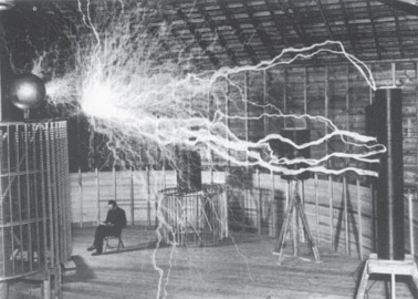
Figure 6.1.
Tesla’s
magnifying
transmitter
operating, with
Tesla sitting in the
background.
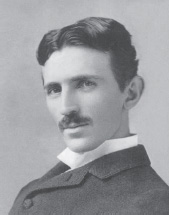
Figure 6.2.
Nikola Tesla in 1894
at age thirty-eight.
Tesla’s reference to etheric sound waves implies an ether medium that is compressible and that transmits waves longitudinally, much as air transmits sound.
The ether he visualized was very different from the elastic solid ether proposed by the nineteenth-century ether physicists that was supposed to transmit electromagnetic waves by means of transverse stresses in its lattice, creating forces perpendicular to the direction of wave propagation.
Tesla adopted this different view because the forces produced by his shocks were directed longitudinally, not transversely.
As such, his concept of the ether comes close to the transmuting ether idea suggested in subquantum kinetics, which views a local energy potential as a localized high or low etheron concentration and an energy potential wave as a propagating etheron concentration magnitude.
The alternate increase and decrease of etheron concentration that would characterize a passing wave very much resembles Tesla’s idea of alternate compression and rarefaction of an ether gas.
Tesla ascribed the longitudinal forces he observed to the action of ether currents propelled forward by the ether shocks he was generating.
However, as is suggested below, the net force imparted by these impulses is more likely due to the action of the potential gradient (the etheron concentration gradient) rather than to any mechanical momentum-type action arising from an associated ether wind.
Experiments performed by Eugene Podkletnov and his coworkers at a laboratory in Russia provide yet another example of the existence of the electrogravitic impulse effect.
Using his knowledge of crystals and ceramic materials, Podkletnov developed a unique superconducting ceramic material, yttrium-barium-copper-oxide (YBa
2
Cu
3
O
7-y
), and conducted a series of experiments in which he emitted high-voltage discharges from an electrode that had been coated with this superconducting material.
In his early experiments, he applied thin coatings of this superconductor to the surfaces of metal spheres having diameters ranging from 25 to 50 centimeters.
He would cryogenically cool a sphere, charge it to 500 kilovolts with a Van de Graaff generator, and then allow it to discharge across a gap to a second metal sphere.
Both were contained in a helium-filled chamber (figure 6.3).
5
He observed that a weak gravitational pulse was emitted that was able to move a newspaper taped to the wall in an adjoining room.
The force did not appear to diminish with distance.
In later experiments, which used a modified version of this spark gap, Podkletnov determined that this force was gravitational in nature.
He succeeded in confining the impulse to a narrow beam that was capable of imparting strong longitudinal forces to very distant test masses.
For these tests, he elaborated on the technology by enclosing his discharge apparatus in a vacuum chamber.
Also, instead of a sphere, he used a 10-centimeter-diameter, 0.8-centimeter-thick superconducting ceramic disc for his emitter (see figure 6.4).
6,
7,
8
The disc was cooled to 50 to 70K, and an inner electromagnet coil induced a “frozen-in” magnetic field oriented perpendicular to the face of the disk to assist in collimating the discharge.
An outer coil that girdled the discharge chamber was used to generate an auxiliary field to further enhance the collimating effect of the inner magnetic field.
Podkletnov then used a Marx capacitor bank to generate a high-voltage electron pulse ranging from 0.5 to 2 mega-volts, which he discharged through the disc and across the evacuated gap toward a 1.5-centimeter-thick copper anode of similar diameter.
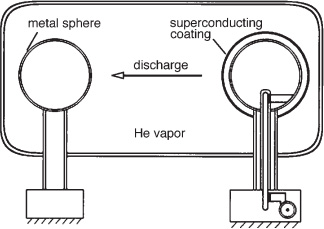
Figure 6.3.
The initial setup of the Podkletnov impulse gravity generator.
(After Podkletnov and Modanese, 2001)
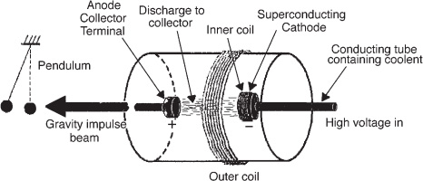
Figure 6.4.
Gravity impulse beam generator developed by Podkletnov.
(After
Cook, Jane’s Defense Weekly, 2002)
When the capacitor bank was discharged, a coherent plane wave was emitted from the superconducting cathode as a flat, 10-centimeter-diameter glowing disc covering the entire electrode surface, which then propagated toward the anode.
Using a laser beam as a sensor, Podkletnov and his associates were able to determine that the discharge had a rise time of less than 100 nanoseconds and a duration of the order of 10 to 100 microseconds.
A gravity shock wave was apparently accompanying this electron discharge.
While the electron discharge terminated at the beam generator’s anode, a gravitational shock wave, apparently accompanying the discharge, would continue in the same direction, passing through the anode unstopped and emerging as a gravity impulse that was confined to a 10-centimeter-diameter beam matching the anode’s cross-section.
When fired with a discharge voltage of 2 million volts, the emitted wave was found to produce a 14-centimeter deflection of an 18.5gram pendulum bob suspended from an 80-centimeter-long thread and placed at a distance of 150 meters from the beam generator.
The beam was able to exert this force after having first passed through a Faraday cage shield, an additional 2½ centimeters of steel, and a 30-centimeter-thick brick wall.
This reminds us of Tesla’s radiant energy shocks, which exerted forces even after having penetrated shields of copper and glass.
A quick calculation indicates that their pendulum bob experienced a momentary repulsive force of about 500,000 g with the passage of each 100-nanosecond shock front.
*17
Pendulum bobs of differing masses and made of various materials (e.g., rubber, glass, plastic, metal) were used, but all deflected by the same amount for a given discharge voltage.
Since force on the pendulum scaled in direct proportion to the pendulum mass, Podkletnov and the physicist Giovanni Modanese concluded the effect they were seeing was gravitational in nature.
9
This mass effect rules out the possibility that momentum is being imparted to the pendulum by electromagnetic radiation pressure.
Furthermore, the amount of electromagnetic energy produced by the discharge is far too small to explain the observed force effects.
These pendulum results also rule out the possibility that this force might be due to a longitudinal “electrokinetic force,” of the sort proposed by American physicist and professor Oleg Jefimenko, which would act only on free charges present in the target material.
10
If the force produced by the gravity impulse beam were due to such electrokinetic ion forces, differing force magnitudes should have been observed when differing pendulum bob materials were tested, and such was not seen.
Figure 6.5 shows the amount of deflection that the pendulum experienced when the gravity beam generator was energized at various voltages.