Secrets of Antigravity Propulsion (43 page)

10.5 • THE CYLINDRICAL SOLITON
This additional, unaccounted-for energy input that was assisting the roller ring’s movement around the stator plate most likely was being entrained from the MEC’s immediate environment.
This hypothesis finds support in the observation that during its operation, the MEC caused a drop in air temperature within a series of nested cylindrical zones established in its immediate vicinity (see figures 10.8 and 10.9).
Here we will attempt to understand how this magnetic wall pattern is generated, and later we will examine how energy from this field pattern might be entrained to power the roller-magnet rotor.
As the roller magnets travel clockwise around the stator plate, they generate an oscillating magnetic field in the stator’s frame of reference.
That is, as a roller magnet coincides with a given reference point on the plate’s circumference, in the stator reference frame the magnetic field strength at that point would increase to a maximum since the flux lines between the oppositely oriented roller and stator magnets attract and complement one another.
However, as the roller makes a half turn in its clockwise motion, its downward return field, which is south-pole seeking, would now occupy the space that formerly held the roller’s north-oriented field.
This same space would also be filled with the stator’s upward-directed south-seeking field.
Since these two fields are in opposition, the net magnetic field strength there would add up to a minimum value.
As a result of the roller magnet’s clockwise motion, the magnetic field in the stator reference frame would sinusoidally vary in magnitude, and would do so without reversing its magnetic polarity (figure 10.14).
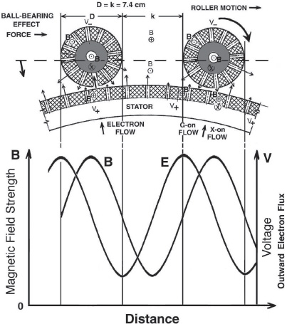
Figure 10.14.
The resonant variation of magnetic field strength
(B) and electric field intensity (E) in the stator reference frame excited by
the circumferential displacement of the MEC’s roller ring.
(P.
LaViolette, ©
2006)
Because the diameter of the roller magnets (
D
) and the space between the roller magnets (
k
) in figure 10.14 are approximately the same, the rotary displacement of this succession of equally spaced roller magnets would set up a resonant oscillation in the stator reference frame.
As an example, when a ring of twenty-three roller magnets revolves at 550 rpm, the generated frequency would equal 211 hertz.
This time-varying field (
B
), in turn, would induce a sinusoidal electric-potential wave oscillation at the same frequency that is directed radially inward and outward from the MEC’s center in the stator’s nonrotating reference frame.
However, compared with the magnetic field maxima, the electric potential maxima would be displaced 90 degrees in phase, that is, by one roller radius in the clockwise direction (see lower trace in figure 10.14).
Also, as discussed earlier, the Faraday disc dynamo effect would be generating a radial electric field gradient across the diameter of the roller magnets with the potential being more negative at the outer periphery of each magnet, thus inducing an electric current to flow radially from the stator through the roller magnets.
Consequently, the sinusoidal AC electric field that the roller magnets generate would modulate this DC-negative potential in the vicinity of the roller ring, causing its amplitude to vary sinusoidally with time.
This is analogous to what was happening in Brown’s electrokinetic apparatus when the high-voltage DC field across the capacitor dielectric was modulated with an AC field from the apparatus’s negative antenna electrode, but in the case of the MEC, the field geometry would be radial rather than axial.
As a result, the electron flow from the MEC’s stator toward its rotor would pulsate at the frequency induced by the translating roller magnets.
When a roller magnet is tangential to a given location on the stator, that is, most proximal to that location, the electric potential that induces current to flow radially outward to the roller would at that moment only be at its median potential.
The potential at that particular location would reach its maximum only after the roller magnet has passed and become displaced by a distance of one roller-magnet radius, so there would be a tendency for arcing to occur on the trailing side of each roller.
This would be especially apparent when a high-voltage gradient was present in the vicinity of the MEC’s rollers, thereby allowing negative ion discharges from the stator to cross large air gaps.
This recurrent outward pulsing of negative charges in some ways resembles the asymmetrical, longitudinal waves radiated from Tesla’s transformers.
The oscillating, nonreversing magnetic field and the oscillating, nonreversing electric field produced around the circumference of the roller magnet ring would induce a longitudinal ELF electromagnetic wave to propagate radially outward from the stator ring in the stator ring plane.
This wave would have a cylindrical wave-propagation geometry, with its magnetic field aligned to the cylinder wall that parallels the roller magnet field and its electric field component oriented perpendicular to the cylinder wall, oscillating radially outward and inward with respect to the center of the MEC.
Roshchin and Godin, however, did not report having observed such radial electric field oscillations in these walls.
Also, this radiated ELF wave would have a circumferential wave component.
Since the stationary wave produced by the rotating roller ring contains a total of twenty-three wavelengths that fit a whole number of times around the roller-ring circumference, a similar whole number of wavelengths would be required to fit around the circumference of field oscillations appearing outside the roller ring.
These would be able to manifest only at multiples of the 0.5-meter stator radius.
At a radius of 1 meter, equal to two stator radii, forty-six wavelengths would fit around the wave’s cylindrical circumference.
At 1.5 meters, equal to three stator radii, sixty-nine wavelengths would fit around the wave pattern circumference, and so on.
No oscillations would manifest at intermediary radial distances because a whole number of wavelengths would be unable to fit into the cylinder circumference at those other radial distances.
This is because Roshchin and Godin used twenty-three magnets in their roller ring, 23 being a prime number.
Hence, oscillating potentials are able to build up to detectable levels only at radii that are whole-number multiples of the stator radius.
At any intermediary radial distances, the oscillations would destructively interfere, hence preventing resonant oscillations from building up there.
The radial ELF oscillations would manifest as a soliton pattern consisting of a series of concentric cylindrical wall nodes similar to those shown in figures 10.8 and 10.9.
Each wall would have a depth of about one roller radius and would be separated from the next wall by a distance of about one stator radius.
The symmetry axis of this cylindrical soliton pattern would be centered on the MEC’s axis of rotation.
Hence, when the MEC’s field patterns are analyzed in this way, it becomes understandable why Roshchin and Godin observed their MEC to be surrounded by a cylindrical, shell-like field pattern.
Although stationary wave patterns that vary in smooth-sine-wave fashion are more commonly observed, patterns with sharp transition boundaries are also known to occur.
For example, such sharp-edged boundaries have been observed in stationary waves produced in the laboratory with Tesla-wave-type oscillations.
14
The waves within each of the soliton’s walls would revolve around the circumference of their walls in synch with the rotation of the roller-magnet ring, remaining stationary with respect to the rotating frame and with respect to circumferential oscillations occurring in the other wall-like nodes.
Hence, the waves in rings at successively greater distances would circuit around the circumference of their walls at successively higher velocities.
The waves circuiting in the 1-meter-radius node, whose circumference would be twice the roller-ring radius, would oscillate at twice the roller-ring fundamental frequency (i.e., at 2
f
o
).
More-distant walls spaced at one-stator-radius intervals would support oscillations circuiting at progressively higher rates, at frequencies of 3
f
o
, 4
f
o
, and so on.
Thus, as one proceeds outward through this soliton wave pattern, moving radially outward from the center of the MEC, one encounters progressively higher harmonic modes, whole-number multiples of the roller magnet’s fundamental frequency
f
o
.
We might also speculate that a whole series of harmonic modes might coexist within each of these walls but at intensities below that of the main harmonic mode circulating in that wall.
Since 23 is a prime number, lower-frequency subharmonic modes, such as
f
o
/2 and
f
o
/3, situated at radii smaller than the roller-ring radius, would not form.
The roller ring would itself be the lowest-frequency resonance in this stationary cylindrical-wave pattern.
Given that Roshchin and Godin observed the walls to extend about 15 meters out from the generator, this indicates that the outermost wall had a frequency of about 30
f
o
.
This would have produced a frequency of about 6,300 hertz for a ring-rotation rate of 550 rpm.
It is remarkable that the soliton pattern was stable enough to produce such a high harmonic.
This 15-meter soliton pattern, though, may limit how close MECs can be placed to one another.
For example, if an aircraft was to employ more than one MEC or SEG for lofting, the units would need to be spaced apart by at least 50 meters.
If Searl had used twenty-two magnets for his inner magnetic ring, then he also would have observed a cylindrical wave pattern forming around his discs, but with twice as many nodes because 22 is not a prime number.
But when divided by two, it yields the prime number 11, so such a disc would have generated nodes at half multiples of the fundamental frequency, with a lowest-frequency node at
f
o
/2 positioned at half a stator radius and with nodes repeating at radial distance intervals of half a stator radius.
10.6 • ENERGY ENTRAINMENT
The MEC’s AC electric and magnetic-field oscillation is induced in a nonlinear medium.
That is, the ferromagnetic material making up the stator and roller magnets has nonlinear electric and magnetic properties.
In addition, the high-voltage discharge that surrounds the stator plate and roller ring when the MEC is operating at high rpm would generate nitric oxide, which also has nonlinear dielectric properties.
As explained in chapter 7, the nonlinear dielectric properties of such plasmas make them good phase-conjugating media.
For example, the phase-conjugating characteristics of the plasma surrounding the dome of Tesla’s magnifying transmitter could explain how his tower was able to “beam” radio-frequency energy to distant locations without appreciable attenuation.
Also, as mentioned earlier, Obolensky has succeeded in phase-conjugating arc fluctuations in an arc lamp by placing a nonlinear reactance element in series with the lamp.
15
This demonstrates that phase conjugation can take place even in the ELF frequency range.
The notion that the MEC was phase-conjugating the ELF waves it was generating, then, seems plausible.
We might presume that some of the MEC’s outgoing ELF radiation was reflected back to the MEC from surfaces in its environment and that these reflected waves were then phase-conjugated by the MEC’s nonlinear media.
The phase-conjugate wave would have retraced the path of the ordinary wave to the remote reflection site and then back to the MEC’s oscillating field.
The ordinary and phase-conjugate ELF waves would have interlocked and constructively reinforced one another to produce phase-locked field potentials that would have manifested at each node of the cylindrical soliton pattern.
One interesting characteristic of a phase-conjugate resonator is its ability to decrease entropy.
For example, in the case of optical and microwave phase conjugation considered in chapter 8, when an outgoing laser (or maser) beam scatters from the environment, its entropy increases—it becomes more disorganized.
The probe beam scattering back toward the phase-conjugate mirror therefore is more disordered than the original outgoing beam.
This state of disorder, however, may be reversed through the emission of the phase conjugate of the probe beam.
That is, the emitted phase-conjugate waves precisely retrace the path of the scattered ordinary waves, causing the entropy of the wave system to decrease as the wave regains its original ordered state.
As a result, energy that normally would be lost through scattering to the environment becomes bottled up in the soliton wave pattern.
As in the case in which microwave phase conjugation is used to generate intense beams for spacecraft propulsion, so too would phase-conjugate resonance occurring in the vicinity of the MEC generator bottle up back-scattered ELF waves, storing their energy in the soliton wave pattern.
The repeating AC oscillations that the roller magnets would generate in the reference frame of the stator plate would then add to one another, causing the soliton’s ELF field oscillations to progressively increase in magnitude.
Experiments have shown that an optical phase-conjugate resonator can self-excite to intensities sixty times that of the input signal beam without any additional energy input, and it has been suggested that even higher amplification coefficients should be achievable.
16,
17
We might speculate that even-greater signal amplification occurs in the MEC.
The faser effect produced by phase conjugation of the ELF waves should amplify not only the MEC’s electric field pulsations in the stator reference frame, but also the associated magnetic field soliton pattern rotating with the roller-magnet ring.
Consequently, since the direction of the soliton’s B field matches that of the roller magnets, the soliton magnetic field should reinforce the roller-magnet fields, causing the ambient magnetic field in the vicinity of the roller magnets to progressively increase over time to far exceed the 0.85-tesla strength produced by the roller magnets alone.
The maximal amount of this induced increase would depend on the rpm of the roller ring, higher ambient field strengths being achieved at higher revolution speeds.
As explained earlier, the radial electric field and current flow induced by the circumferential displacement of the roller magnets depends not only on the roller ring’s rpm but also on the field strength of the magnets.
Since phase-conjugate resonance would boost this field strength, one would expect that the potential developed at a given rotation rate would far exceed the voltage that we calculated earlier on the basis of the Faraday disc effect.
In addition, the radial electric field component of the soliton’s ELF waves would amplify through phase-conjugate resonance, and in the MEC’s nonlinear environment, a portion of this amplified AC potential would likely transfer over to boost the MEC’s DC electric field component.
Consequently, it is possible to imagine that these effects in combination could produce a DC voltage drop in the vicinity of the MEC of tens of thousands of volts or more, rather than just of a few volts.
This would explain the origin of the high-voltage glow discharge that Roshchin and Godin observed even when their 20kilovolt external bias voltage was switched off.
It would also account for the pink, high-voltage glow discharge that Searl observed around his discs.
We are here reminded of Tesla’s towers, which similarly developed potentials so high that nearby objects were excited to luminesce.
Earlier, we concluded that the circumferential displacement of the B fields of the roller magnets induces a radial electron flow from the stator plate to the rollers that, in turn, generates a ball-bearing-motor torque that aids the clockwise rotation of the rollers.
Consequently, the boosting of the radial electric potential gradient due to these various faser effects would proportionately increase the induced-current flow and thereby aid the rotation of the roller ring.
In this way, energy from the soliton-field pattern would be continuously converted into mechanical energy, inducing the roller ring to accelerate in spite of resistive losses.
This additional energy input into the MEC is illustrated by the feedback loop on the right side of figure 10.13.
Since this array of magnetic-wall solitons is part of a single resonance phenomenon, these resonant modes should exchange energy with one another.
Hence, the buildup of potential energy in the vicinity of the roller ring (the inner soliton cylindrical wall that was assisting roller propulsion) could easily be conveyed from the other cylindrical wall nodes whose frequencies resonated harmonically with this base frequency.
The temperature drop observed in the magnetic walls may be a direct result of thermal energy being extracted from the air and being entrained into the soliton throughout its harmonic range.
If so, the soliton field must then somehow be physically interacting with the air molecules in the magnetic walls and possibly be drawing energy from their Brownian motion.
For example, the magnetic field oscillating in the cylindrical walls might slightly magnetize the air or solid objects that a wall happened to intercept, and magnetized molecules whose Brownian-motion oscillation happened to match any of the wall’s ELF harmonics would then have their energy entrained into the soliton.
Consider, for example, an inner wall located 1 meter from the MEC’s axis.
It would support an ELF frequency of 2
f
o
, twice the fundamental frequency.
However, this particular harmonic could be excited by an entire spectrum of harmonics existing in the ambient molecular movement:
f
o
, 2
f
o
, 3
f
o
, 4
f
o
, 5
f
o
, and so on, up to the ninth harmonic; recall the discussion in chapter 8.
Thus, there are abundant opportunities for frequency matches to develop.
Using the heat capacity of air, Roshchin and Godin have estimated that heat was being lost at the rate of 1,700 calories per second from the eight innermost magnetic walls residing within 4 meters of the MEC’s center.
*31
This loss rate equals 7 kilowatts, which slightly exceeds the 6 kilowatts of electric power that the MEC was mysteriously generating without any mechanical input.
If the caloric loss of the entire soliton pattern is taken into account out to a radius of 15 meters, then there is more than enough energy loss to account for the MEC’s source of power.
Thus, the MEC may have a clearly identifiable energy source in its immediate environment.
It would be partially propelled by heat flowing into the magnetic walls from the ambient air and laboratory structures, with this energy being subsequently entrained into the soliton pattern.
A generator such as this that cools its environment while it generates power appears to be the ultimate solution for the global warming problem.
It is also possible that the MEC is entraining background electromagnetic energy.
The universe is permeated by energy spanning a wide range of frequencies, including frequencies in the ELF range.
Also, there is the well-known ionospheric Schumann resonance, which is excited at approximately 8 hertz by solar particle bombardment of the ionosphere.
Higher harmonics of this resonance might match some of the soliton harmonics.
The MEC may also be cohering energy from the omnipresent zero-point energy background that extends throughout space.
As was noted in chapter 4, the reactive ether of subquantum kinetics is conceived to have X, Y, and G reactant concentrations that continually fluctuate in magnitude in seemingly random fashion.
The X and Y ether fluctuations correspond to spontaneous pulsations of the ambient electric potential field, and the G ether fluctuations correspond to spontaneous pulsations of the ambient gravity potential field.
Together they make up the zero-point energy continuum.
It seems plausible that the zero-point energy background would locally transfer a portion of its energy to material bodies it surrounds, so that if there was a decrease in the energy density of the zero-point energy background, then one might observe a corresponding local decrease in air temperature.
Thus, if the MEC was cohering energy from the zero-point energy background, the observed drop in air temperature might be a collateral effect and not the actual source of the MEC’s energy.
If it was able to extract energy directly from the zero-point energy background, then the MEC would be able to continue powering itself even in empty space.
The subquantum kinetics zero-point energy spectrum differs from that of conventional physics in that it spans all frequencies, including ELF frequencies.
The zero-point energy concept of quantum mechanics and quantum field theory, for example, predicts that such fluctuations should instead occur primarily at high energies since such fluctuations are theorized to arise in the simultaneous appearance of a virtual subatomic particle and its virtual antiparticle.
Most of the energy in the conventional zero-point energy spectrum then would be at frequencies greater than 10
20
hertz (the MeV range) and would extend on up to the Planck limit of 10
43
hertz (10
28
electron volts).
Conventional physics, then, would be off by at least eighteen orders of magnitude in providing an appropriate frequency match for the MEC’s energy extraction.
Subquantum kinetics, on the other hand, allows energy to be extracted from the fluctuating ether at frequencies in this ELF range and even lower.
In fact, in subquantum kinetics, the probability of a fluctuation occurring increases as frequency decreases.
High-energy fluctuations in the MeV range and greater that would be potentially large enough to nucleate the materialization of a subatomic particle would be exceedingly rare events.
If we define our system boundary so that it surrounds both the MEC and the magnetic-wall soliton pattern that it creates in its immediate vicinity, we find that the Searl effect does not violate the first law of thermodynamics, but it does violate the second law of thermodynamics.
However, the violation of the second law is the expected norm whenever phase-conjugate resonance is occurring.