Secrets of Antigravity Propulsion (41 page)

Figure 10.5.
How water peaks beneath a low-hovering UFO, as based on numerous eyewitness reports.
(After Sigma,
Ether Technology
80)
One geologist speculated that the shock waves from a local 3.0Richter earthquake spontaneously focused their energy to this spot and caused the massive chunk of soil to pop out, but seismologists found this unlikely.
Besides, for this to happen, nature would have to violate the law of entropy.
For this multi-ton piece of soil to move intact without breaking apart, it must have been subject to a uniform force pulling all of its mass upward, countering a downward gravitational pull of at least 90 grams per square centimeter.
This would be about two hundred times greater than the lift force developed beneath Brown’s 6-inch-diameter (15-centimeter) AC electrokinetic test apparatus.
Since this event took place on a remote farm field at a time when no observers were present, no UFO sighting was reported.
Nevertheless, the physical evidence at the site was consistent with the UFO soil-displacement scenario that Schaffranke had documented seven years earlier.
The craft must have hovered near the ground, with its electrogravitic field penetrating the soil below.
Then as the craft rose, this extended field gradient would have moved up as well, inadvertently drawing up this chunk of soil with it.
As the craft slowly swung in an arc-like trajectory across the field, pieces of soil dribbling from the bottom of this hovering chunk would have floated to the ground.
Eventually, the craft must have accelerated, leaving the soil chunk to break away from its towing field and thump to the ground at its new location.
What would otherwise be a mystery becomes easily explainable when one has a foreknowledge of gravity field propulsion technologies.
Nevertheless, it leaves us to marvel at the enormous lift that such an antigravity field can generate, one capable of overpowering the natural force of gravity to allow tons of soil and a massive spacecraft to float freely.
Whether it was made by us or came from somewhere else maybe we will never know.
10.2 • THE MAGNETIC ENERGY CONVERTER
The Russian physicists Vladimir Roshchin and Serge Godin in the mid-1990s built and tested a version of the SEG, which they named the magnetic energy converter (MEC).
It resembled one of Searl’s earlier generators, consisting of a single magnetized stator ring measuring 1 meter in diameter flanked by twenty-three roller magnets, each having a diameter of 7.4 centimeters; see figure 10.6.
7,
8
Roshchin and Godin’s generator differed from Searl’s in several respects, the principal difference being in the design of the runner magnets.
They refer to the runners as rollers, so I will use their term instead.
Searl used a special magnetization technique to create magnetic spoke domains in the cylindrical sides of his runner magnets oriented perpendicular to the runner’s axis of rotation.
The MEC accomplished the same thing with dipole magnets implanted perpendicular to the surface of each roller magnet so that the north pole of each magnet was oriented perpendicular to the stator plate.
The stator had a complementary set of dipole spokes with their north pole pointing out toward the rollers.
As in Searl’s SEG, these mutually repulsive magnetic domains helped to orient the rollers as they revolved around the circumference of the stator plate and helped to keep the rollers from contacting the plate.
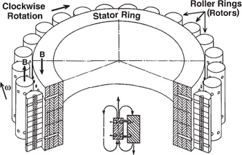
Figure 10.6.
The magnetic energy converter.
(Based on a
drawing by V.
Roshchin and S.
Godin, 2000)
The axles of the roller magnets were secured via bearings to a common rotor frame that kept each roller at its proper relative spacing as they rotated around the stator ring.
The rotor had a shaft that was connected to an electric motor via a clutch mechanism.
As in Searl’s experiments, the motor was used to get the generator up to speed.
Roshchin and Godin found that the MEC had a specific rotational speed at which it began to partially power itself, with its drive motor accordingly consuming less power.
This occurred when the rotor speed surpassed about 200 revolutions per minute (3.3 hertz).
After about one and a half minutes, the rotor had accelerated to 550 revolutions per minute (rpm), at which point the starter motor current consumption had reached zero and was beginning to go negative.
The clutch assembly was then made to disconnect the motor from the rotor shaft and in its place connect a generator.
As the rotor continued to accelerate, an increasing load was applied to the generator, reaching 7 kilowatts by the time the rotor had a reached a speed of 595 rpm.
Greater loads caused the rotor speed to subsequently decline.
At greater than 590 rpm, the MEC made “an unpleasant high frequency whistling sound” that damped out as soon as an increased electric load was placed on the generator.
Roshchin and Godin also found that the weight of the generator assembly decreased as the rotor accelerated.
Weight loss first became noticeable when the rotor speed reached its critical value of 200 rpm, and by the time its speed had reached 450 rpm, weight loss began to increase exponentially (figure 10.7).
At 550 rpm, there was an inflection pause in the weight-loss curve and after 590 rpm, an extremely steep rise in weight loss with increasing rotor speed.
By the time the rotor speed had reached 595 rpm, the apparatus as a whole had become 35 percent lighter, with the weight of the generator alone dropping 50 percent.
There was substantial hysteresis in this weight loss–rotation rate curve.
As rotor speed decreased from 595 to 400 rpm, weight loss remained constant at the 35 percent reduction level.
Measurements were not made at greater than 600 rpm for fear that the MEC
would enter an uncontrollable supercritical regime in which positive feedback
would cause an exponential rise in rotor speed.
A similar positive feedback mode had resulted in Searl losing several of his devices through uncontrolled levitation.
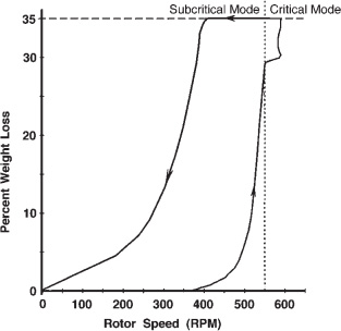
Figure 10.7.
Weight loss as a function of rotor speed when a 20-kilovolt potential was applied between the plate and the rollers of an MEC.
(After Roshchin and Godin, 2000)
The MEC was found to produce this weight-loss effect only in clockwise rotation (for rollers with their north pole oriented up).
Counterclockwise rotation produced a weight-gain effect, with the gain in weight being proportional to the rotor speed.
Roshchin and Godin found that application of a 20,000-volt bias potential applied between the plate and the roller magnets improved the performance of the MEC, allowing its weight reduction to begin to take effect at a lower rotor speed.
This potential would have ionized the air around the MEC, allowing the electron current to flow more easily across the 1-centimeter gap between the stator and the rollers.
Like the SEG, the MEC generated a luminescence around itself when seen operating in the dark.
The bluish pink ionization cloud was observed to cover both the stator ring and the roller magnet ring.
Also, when looking at the edge of the rotating roller magnet ring, Roshchin and Godin saw, superimposed on this emission, a series of horizontal, yellowish white luminescent bands (four or five) spaced along the height of the roller magnet’s cylindrical surface.
This luminescence suggests a possible high-voltage electron discharge from the surface of the roller magnets, although it was not accompanied by sounds characteristic of arc discharge.
This silent emission could occur because the emission was coming from a large surface area, rather than from a point source.
They compare it to high-voltage, microwave-induced luminescence observed prior to the point of electric breakdown.
Roshchin and Godin also found that when in operation, the MEC surrounded itself with a stationary magnetic-wave pattern consisting of a nested series of cylindrical “magnetic walls” (see figures 10.8 and 10.9).
9
Magnetometer measurements indicated the presence of a magnetic-field flux inside the walls of 0.05 tesla, with the field orientation being the same as that of the roller magnets and at about 6 percent of their 0.85 tesla magnetic flux.
No magnetic flux was detectable outside of the walls.
There is no evidence to suggest that the magnetic-wall pattern is hazardous in any way.
Roshchin and Godin did not notice any harmful effects.
On the contrary, Searl has reported that the field emissions of his SEG actually had healing effects.
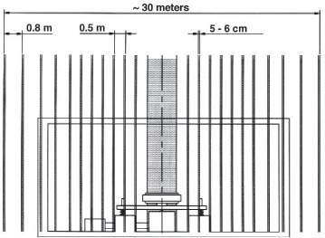
Figure 10.8.
A side view of an MEC and its research lab, showing the positions of the nested magnetic walls.
(After Roshchin and Godin, 2000)
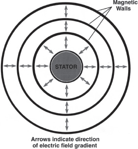
Figure 10.9.
A top-down view of the layout of the cylindrical magnetic walls that together formed a stationary wave pattern around an MEC stator ring.
(P.
LaViolette, © 2006)
The magnetic-wall pattern extended out from the MEC’s stator ring for a distance of up to 15 meters, beyond which the magnetic flux within successive walls rapidly decreased in intensity.
The field pattern could be sensed on the second floor of the laboratory, indicating that the walls extended upward at least to a height of 6 meters and possibly downward into the ground for a similar distance.
The innermost walls were spaced from one another by approximately 0.5 meter (one stator radius), and this spacing increased 0.8 meter as distance from the MEC increased.
Also, the walls had a thickness of about 5 to 6 centimeters, approximating the 7.4-centimeter-diameter of the roller magnets.
The proximity of these dimensions to that of the ring of roller magnets led Roshchin and Godin to conclude that there was a direct connection between this stationary field pattern and the circumferential movement of the magnetic rollers.
This conclusion was also supported by their observation that there was a decrease in air temperature within the magnetic walls, which could be immediately felt by placing one’s hand within a wall.
Moreover, they found that the temperature decreased in proportion to the rate of roller-ring rotation, the decline becoming noticeable above a rotor speed of 200 rpm and reaching –7.5°C by the time the rotor speed had reached 550 rpm.
Consequently, they concluded that energy from the environment was somehow being transferred to the ring of roller magnets to assist their rotation.
Below, I will attempt to explain the principle of how the MEC generator operates, with the understanding that the same explanation should apply equally well to the SEG.
These ideas were first presented in June 2001 at the Conference on New Hydrogen Technologies and Space Drives.
10
Briefly, clockwise rotation of the rollers causes a current to flow radially outward from the MEC’s plate to its rollers due to the Faraday disc dynamo effect.
As a result of the “ball-bearing motor effect,” this current then creates a torque that induces the rollers to continue their clockwise rotation.
The rotating rollers create resonant extremely low-frequency (ELF) oscillations that phase-conjugate to form an extended soliton wave pattern.
Energy entrained from this soliton helps to propel the rollers.
Let us begin by examining the Faraday effect.