125 Physics Projects for the Evil Genius (68 page)
Read 125 Physics Projects for the Evil Genius Online
Authors: Jerry Silver

Figure 116-1
Diode test circuit
.
This relationship between current and voltage is exponential.
The current that passes through a diode is related to the voltage applied across it by the diode equation:
I = I
o
e
qV/kT
where
I
is the current and
V
is the voltage (
q
and
k
are constants,
T
is the diode temperature, and
I
o
is a property of the diode).
This equation shows that the current increases exponentially as the voltage is increased. At first the change is slow. But after about 0.7 V, the diode offers little resistance to the flow of current.
Plot the current versus voltage on a linear plot. Its shape is exponential with a “knee” around 0.7 V defining a region where a small increase in voltage causes a very large increase in current. If you plot the log of the current versus the voltage, you should get a straight line at least over a major part of the data range. If voltage is a logarithmic function of current, current is an exponential function of voltage. Plotting this confirms the nonlinear behavior of the diode characteristic.
What happens if you swap the two leads of the diode? This applies a voltage in the opposite direction as in the previous case. As a one-way valve, the diode does not allow any measurable current to flow in the reverse direction. If you try to force the issue and continue to increase the voltage (going the wrong way), you may (depending on the diode) reach a condition called the
breakdown voltage
. When this happens, the opposition to the current flow breaks down and the diode allows the current to flow. In many diodes, this is a reversible condition, which can be used to establish a set voltage level in a circuit. Going into breakdown may damage some diodes, so be careful if you try to measure this in your circuit.
A diode is a nonlinear device. A small increase in voltage produces a large increase in current, which grows exponentially with voltage.
The Earth
Measuring the Earth’s magnetic field
.
The Earth has a magnetic field that goes from the South Pole to the North Pole. The
magnetic
South Pole is actually close to the
geographic
North Pole. We can measure how strong the horizontal component of the Earth’s magnetic field is by comparing its effect to that of a magnetic field produced by the current flowing in a coil of wire.
- insulated wire several meters in length
- compass, preferably one mounted on a low-friction pivot
- ruler
- protractor
- cylindrical shape to wrap the coil (The diameter of the shape depends on the length of the compass needle. The diameter of the coil needs to be larger than the length of the compass needle.)
- ring stand or other support to hold the coil of wire
- DC power supply capable of current in the range of 1.0 amp or higher
- DC-ammeter or a multimeter configured as an ammeter in the 0–10 A range
- room with nonferrous tables and free of stray magnetic fields
1. Set up the compass. Make sure it is free-spinning and
pointing to the north
. Metal desks containing iron or steel may interfere with this. Also, motors or loudspeakers may have significant magnetic fields that could affect the outcome of this measurement.
2. Form a coil of 15 turns using the cylindrical shape to form the coil. (For a small hand-held compass, a 1½ inch diameter pipe is a good form. For the pivot type compass, a soup can or coffee can is more appropriate.) After the coil is formed, withdraw the object used to wind the coil. Leave some wire at the start and end of the coil to allow it to be connected into a circuit.
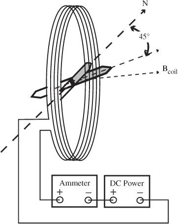
3. Support the coil using a ring stand or other support. The coil is oriented vertically with
the plane of the coil facing east and west. The compass should be contained inside the plane of the coil, as shown in
Figure 117-1
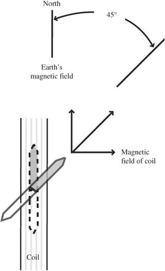
. A top view of this is shown in
Figure 117-2
for clarity. Notice the ends of the compass points to the turns of the coil.
4. Make sure the DC power supply is turned off and the ammeter is set to read currents in the range of 1–10 amps.
5. After stripping the insulation from the ends of the coil, attach one end to the positive terminal of the ammeter and the other end to the negative terminal of the DC power supply. You can use jumper wires or attach the coil directly. Refer to
Figures 117-1
and
117-2
for the appropriate connections.
6. Complete the electrical circuit by connecting the negative terminal of the ammeter to the positive terminal of the DC power supply.
7. Place the protractor so the zero degree line ins aligned with the direction the compass exposed only to the Earth’s magnetic field.

Figure 117-1
Set up for measuring the Earth’s magnetic field (side view)
.

Figure 117-2
Set up for measuring the Earth’s magnetic field (top view)
.
8. Slowly and carefully turn on the DC power supply. Increase the current reading on the ammeter until the compass needle deflects 45 degrees from its starting position.
9. At this point, the horizontal component of the Earth’s magnetic field is balanced by and equal to the magnetic field of the coil.
The Earth’s magnetic field is:

Expected Results(1.26 × 10
−6
is the same as 0.0000126 and you can multiply inches by 0.00254 to get meters.)
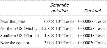
The Earth’s magnetic field varies with location, but it is in the ballpark of about 5 micro Teslas or 5 μT or 5 × 10
−7
T. The following table summarizes the results for different latitudes, and it includes the scientific notation and decimal forms that are equivalent.

The magnetic field of the coil is perpendicular to the plane of the coil. In this experiment, the magnetic field of the coil is perpendicular to the horizontal component of the magnetic field of the Earth. When the coil’s magnetic field just equals the horizontal component of the Earth’s magnetic field, the resultant points at a 45-degree angle between the two. When this occurs, the magnetic field of the Earth is given by that of the coil according to the equation:

where
B
is the coil’s magnetic field in Teslas
N
is the number of turns in the coil
μ
o
is a measure of how strong a magnetic field is produced by a given current, called the
permeability of free space
, and equals 1.26 × 10
−6
Teslas
I
is the current in amps
R
is the radius of the coil in meters.
As an example: A 15-turn coil that is 2 inches in diameter (or 0.051 meters) requires a current of 0.28 amps to turn the compass 45 degrees.
The magnetic field is:
B = (15 turns × 1.26 × 10
−6
T-m/A × 0.28A)/ (2 × 0.051m)
= 0.00000052 T or 5.2 × 10
−5
T
This is in the ballpark of the expected range for the Earth’s magnetic field for middle latitudes.
The previously measured value is the horizontal component of the Earth’s magnetic field. Near the equator, the Earth’s magnetic field is all horizontal. As you approach the poles, the direction of the magnetic field with respect to the Earth’s surface increases. The angle the field makes with the Earth’s surface can be measured using a compass that is free to rotate in the vertical plane. The total field (or the overall field strength vector) at that location can be determined from:
total field (Teslas) = horizontal component (Teslas) / cosine (angle to horizontal)
As with many experiments, it is comforting to know that the effect we intend to measure is, in fact, what our experimental results are giving us. One way to increase confidence in our results is to repeat it under different condition and verify we have the same outcome. According to our model, it should not matter how many coils we have. Repeating the measurement to see how much current is needed to turn the compass 45 degrees using 5, 10, or 20 coils should give a consistent result as the measurement described about using 15 coils.